Generator remote start hack

DISCLAIMER
Carbon monixide is very poisonous and can kill quickly! Under no circumstances I will be held responsible or liable in any way for any claims, damages, losses, death, expenses, costs or liabilities whatsoever!
Leaving in the countryside has many good sides, the power grid connection not being one of these. A strong thunderstorm is enough the get bumpy outages, and sometimes the power goes away even for several hours!
That could turn a rainy work from home day into a forced rainy vacation day.
So I decided to buy a cheap power generator, and to tweak it into a fully automatic mains backup.
The plan
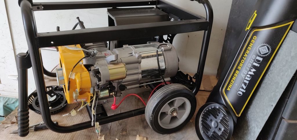
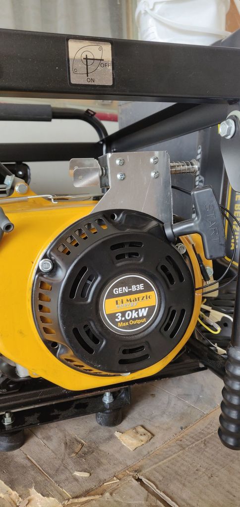
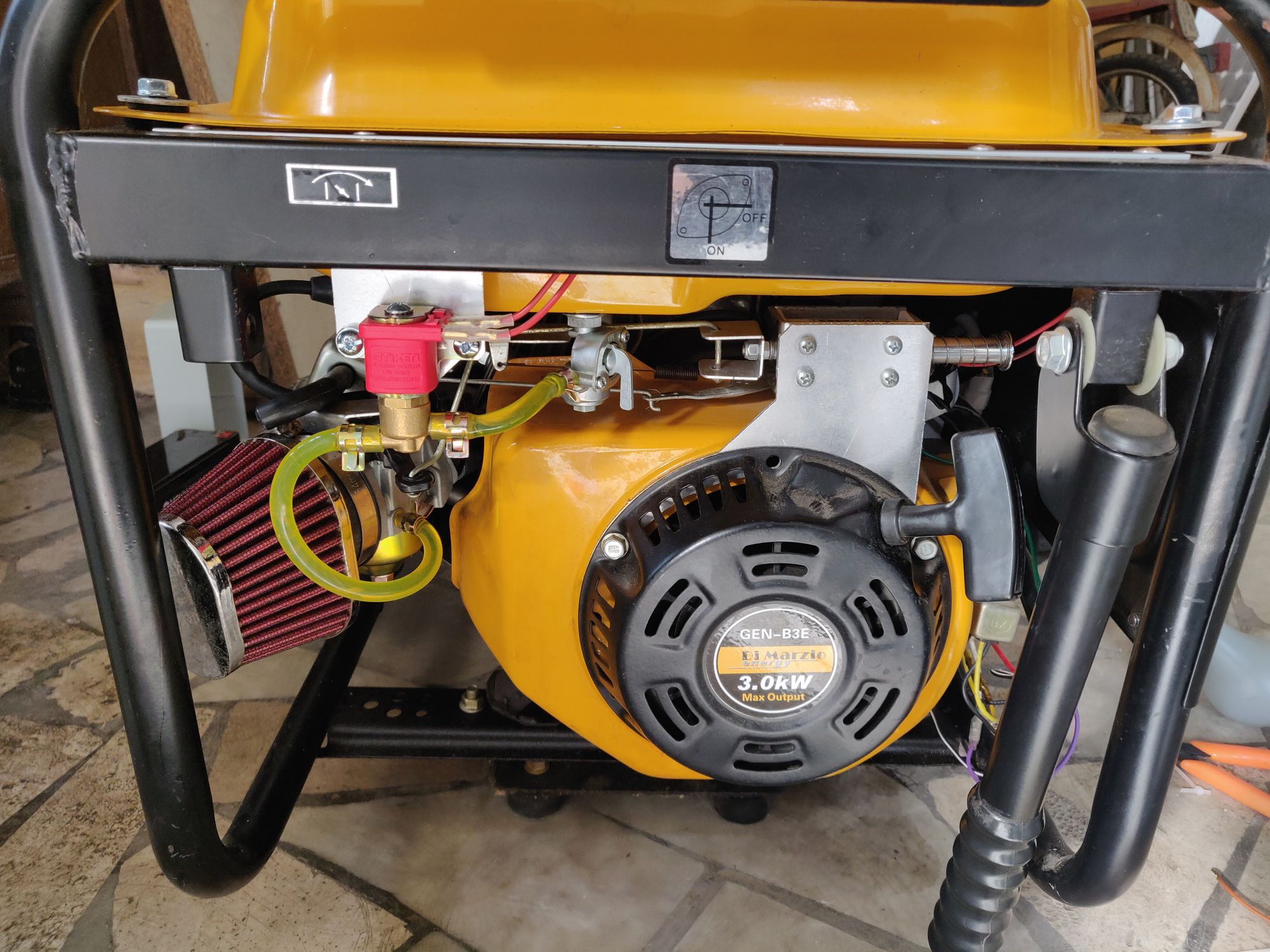
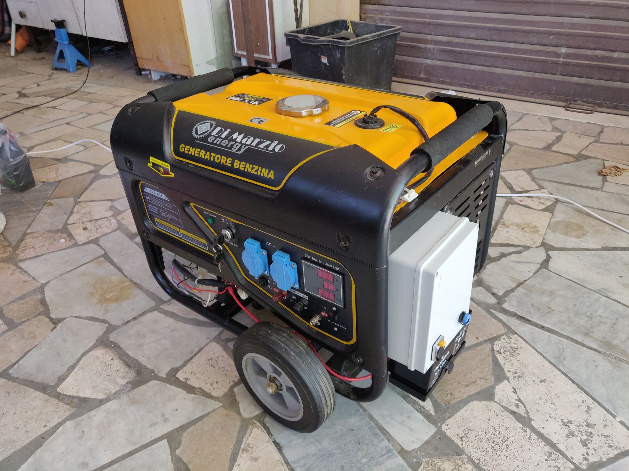
I've chosen a Di Marzio GEN-B3E which is a 3kW, electric start gasoline generator:
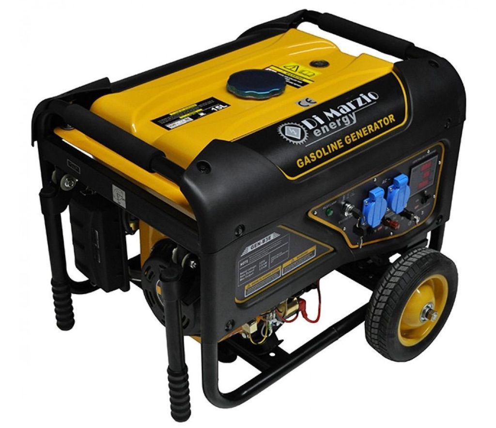
It's a GX200 Chinese Honda clone (Chonda), with electric start - which should be easier to tweak into a fully autonomous generator, as it already includes a starter engine.
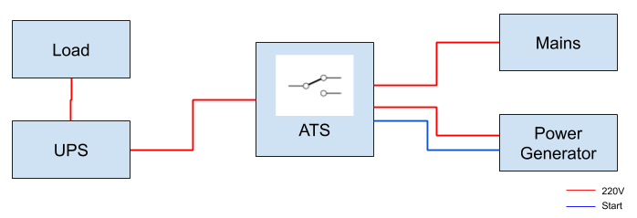
Said so, here is the plan:
-
Load
In my case the load is a small rack containing my backup infrastructure. It consumes ~300W. -
UPS
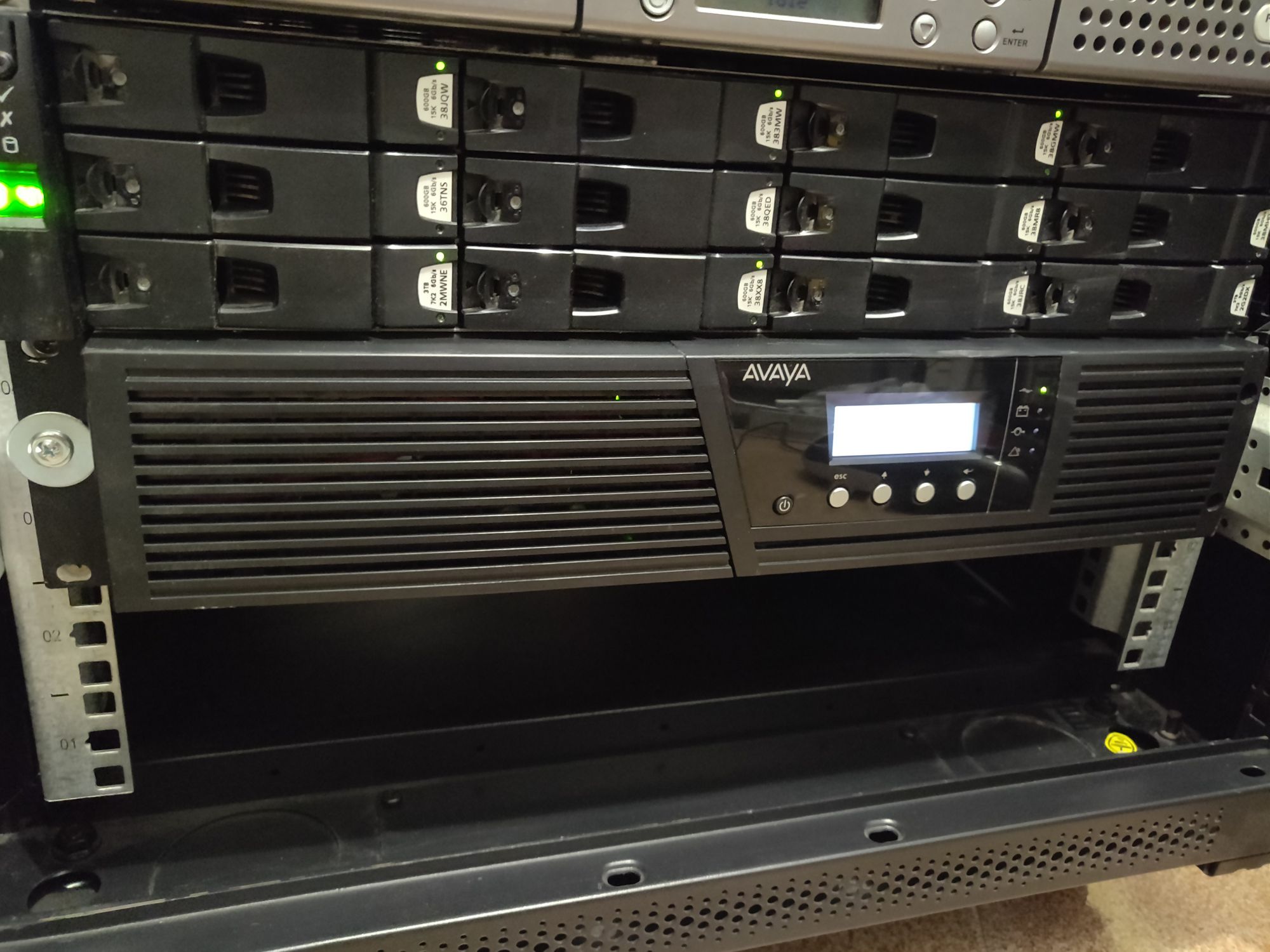
A UPS is needed to protect the load from mains instability as well as keeping it alive in between a main failure and the power generator ramp up. Generator frequency is adjusted via a mechanical governor, which makes it fluctuate around 50Hz - which is something many line-interactive UPSes won't like. An on-line UPS instead will accept a wide frequency and voltage range as input, which makes it ideal for this application. In my case I'm using an Avaya (Eaton) 9130 ups to protect the load:
-
ATS
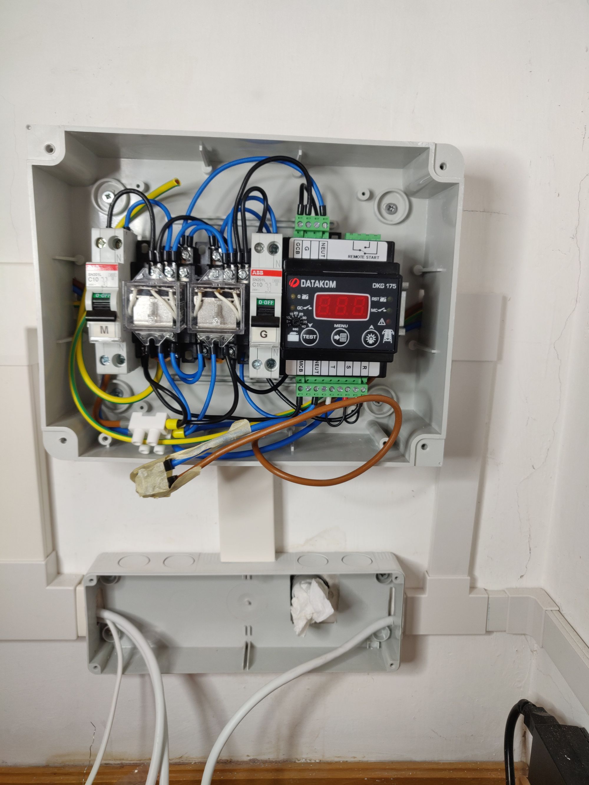
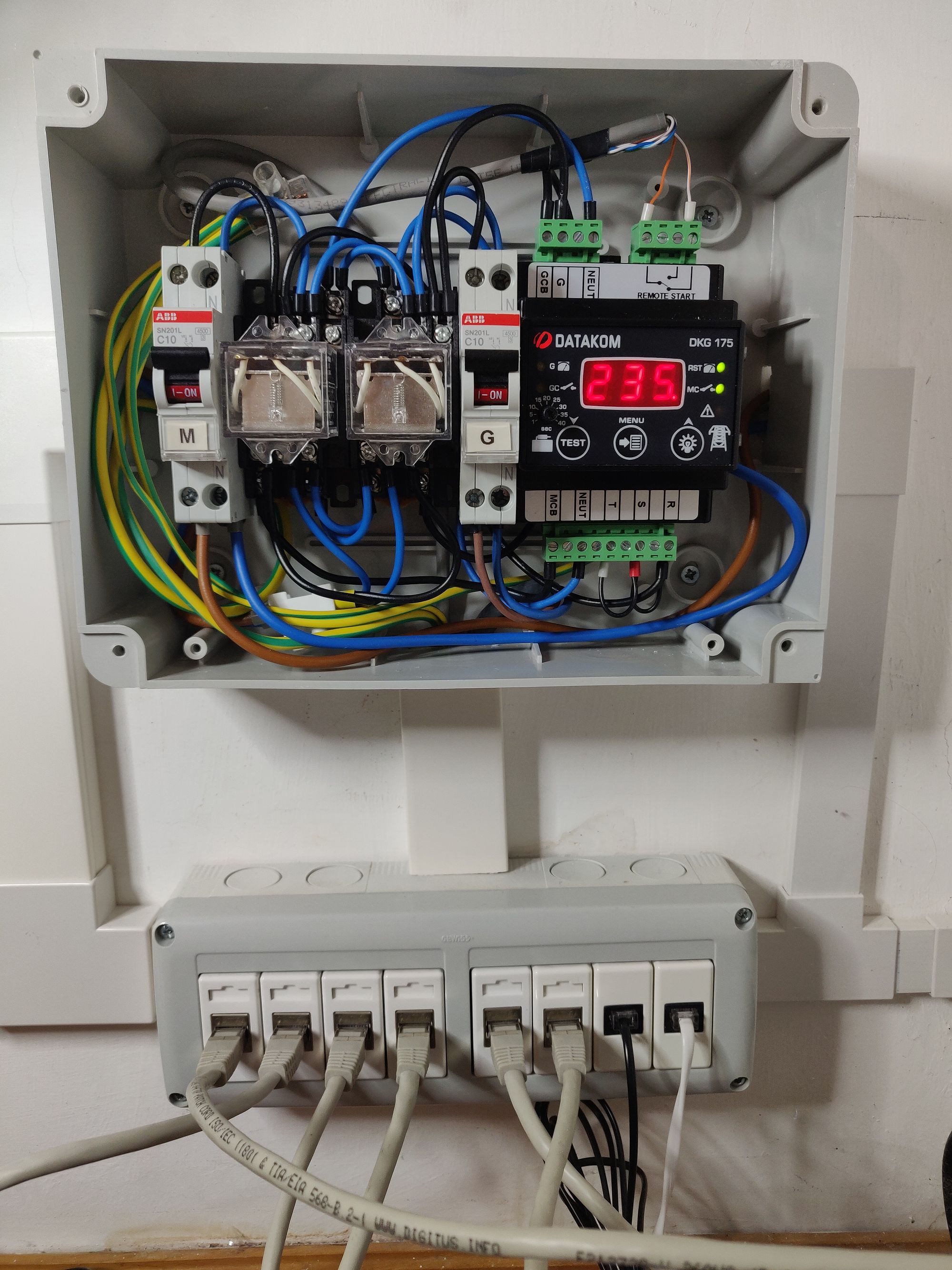
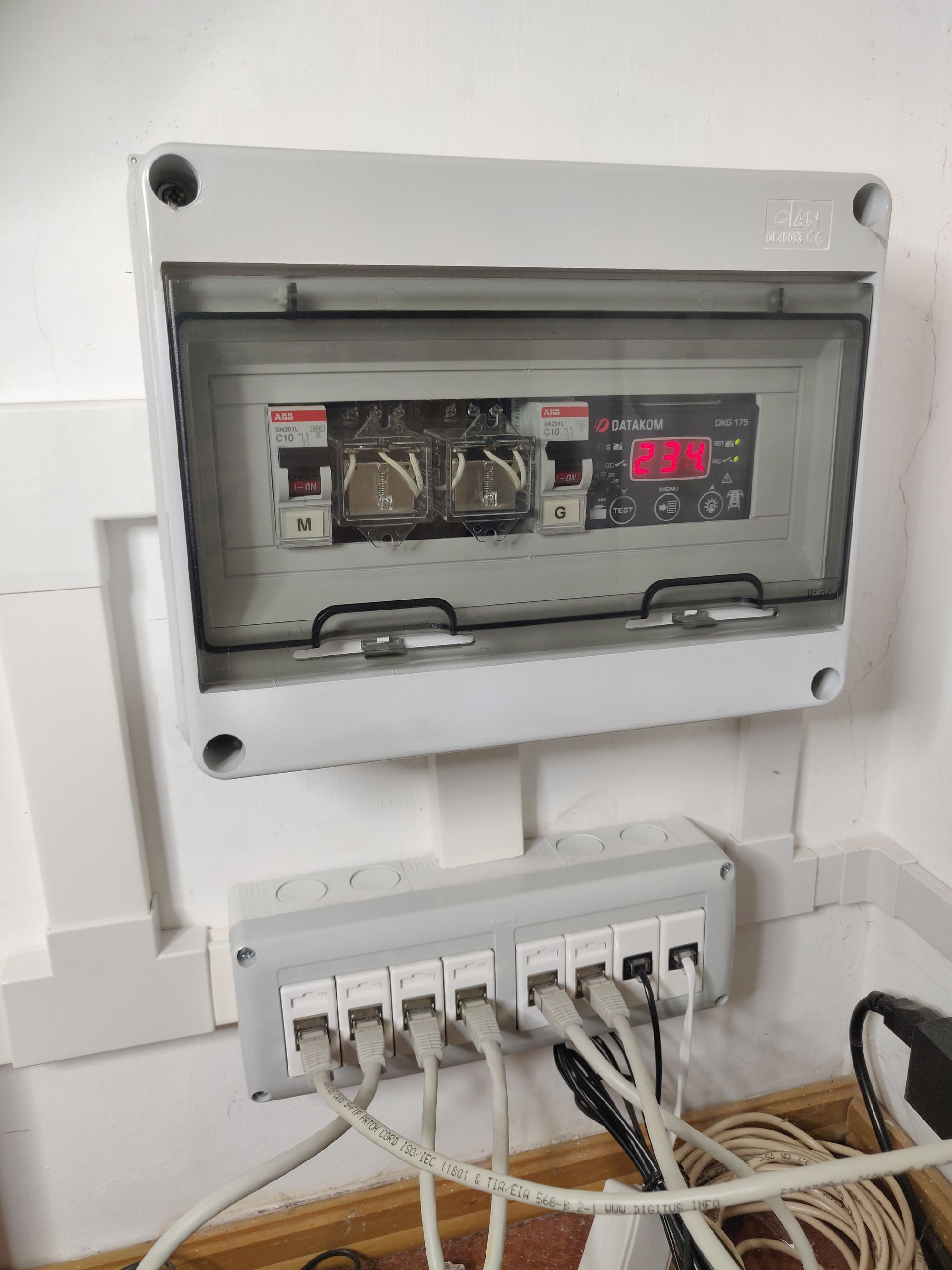
I've added an electric panel featuring the ATS switch. I've chosen a Datakom DKG-175.
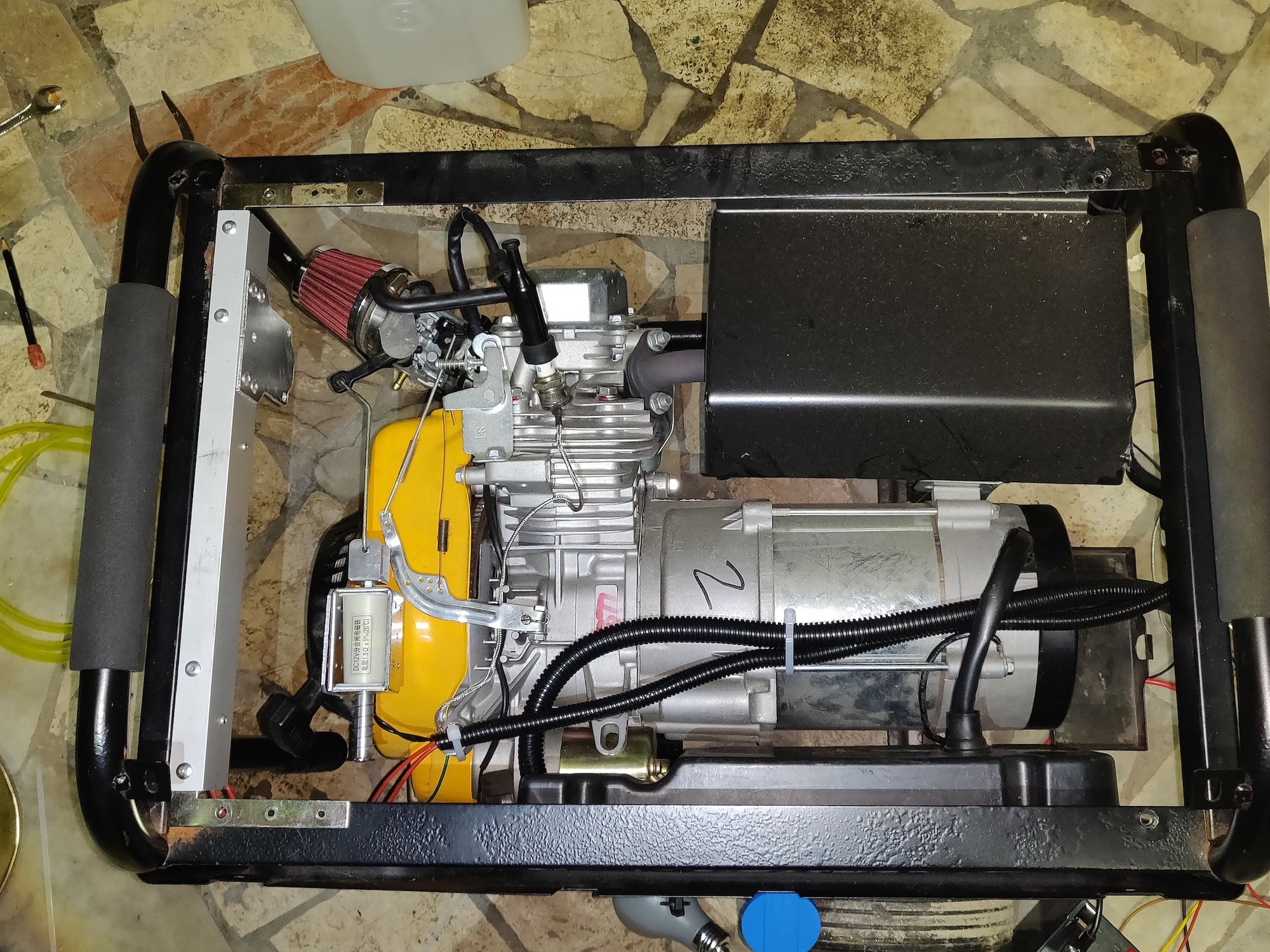
Hacking the choke
To start the generator, you need to close the choke for some seconds and feed the engine with a rich mixture. Unfortunately on my generator (and generally on all the GX200 Honda clone-powered generators I've seen around), the choke lever is extended upwards to make some space for the air filter, and that makes a reliable mechanism to push/pull harder to implement:
So I've decided to replace the air filter and use a flat choke lever:
-
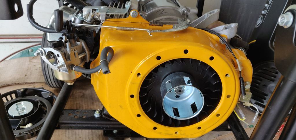
Disassemble the air filter to get access to the carburetor, and the recoil rope:
-
Replace the standard choke lever with a "flat" one (can be found on ebay):


-
Replace the air filter as now it won't fit anymore. I've used a Lamp 06701:

-
Get some solenoid that we'll use as actuator. I've found these 12v 35mm ones on eBay:
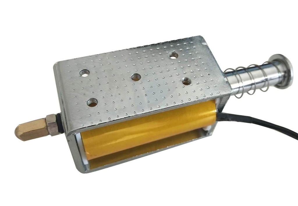
-
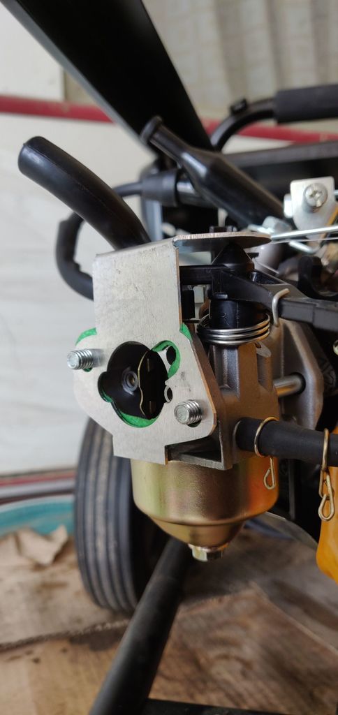
Machine some pieces to keep things in place. I've used a 3mm aluminium sheet: (SVGs: solenoid support, rod arm, choke lever support):


-
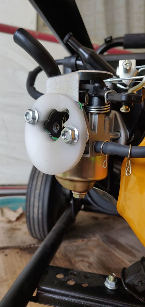
Machine a support to connect the new air filter. I've used some hard plastic I had around (SVG):

-
Put the solenoid in place:
-
Bend a rod to transmit the motion from the solenoid to the choke lever:


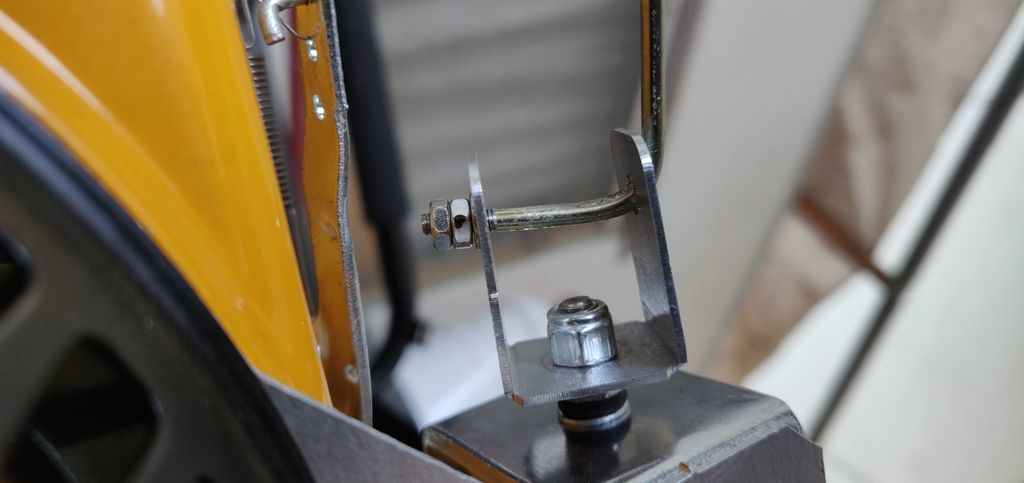
-
Add the choke lever gasket:
-
Mount the new air filter:
Done! Now let's check it works properly:
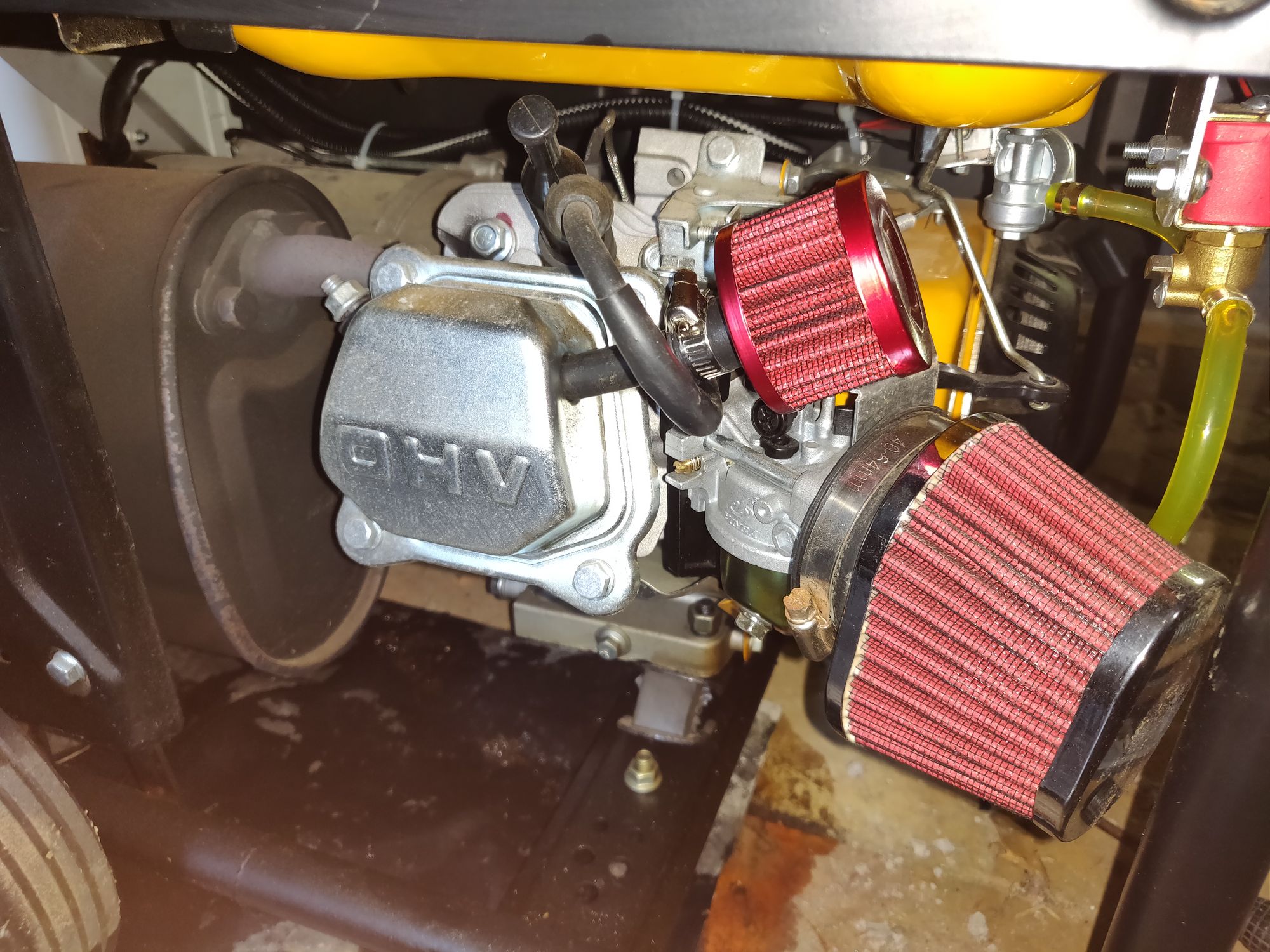
Update: my friend Enrique told me that it's not wise to leave the breather pipe unplugged like that: some insect could make his nest there, so I've decided to add a small air filter to protect it:
Hacking the fuel line
Thanks to my friend Enrique, I understood how important is to shut off the gas when the generator is off.
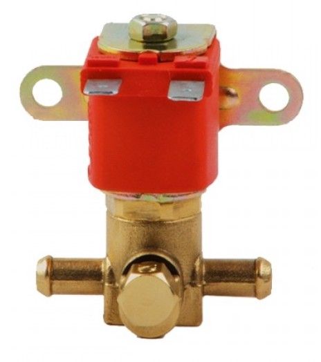
So I went on and found a gas solenoid. As Enrique suggested, it is important to pick one that will work without flow pressure, as the generator fuel line has a very low pressure. I've found a suitable Atiker solenoid on eBay:
Then I've milled a support to hold it in place (SVG):

And finally installed it:
The fuel solenoid could stay open for long time because it's energized when the generator runs - so we'll use PWM, similarly to what we did for the choke, to keep the fuel open without overheating it.
Hacking electronics
With the choke fixed, it's time to put electronics in place; but first let's add a couple of sensors that will make the whole safer to operate:
-
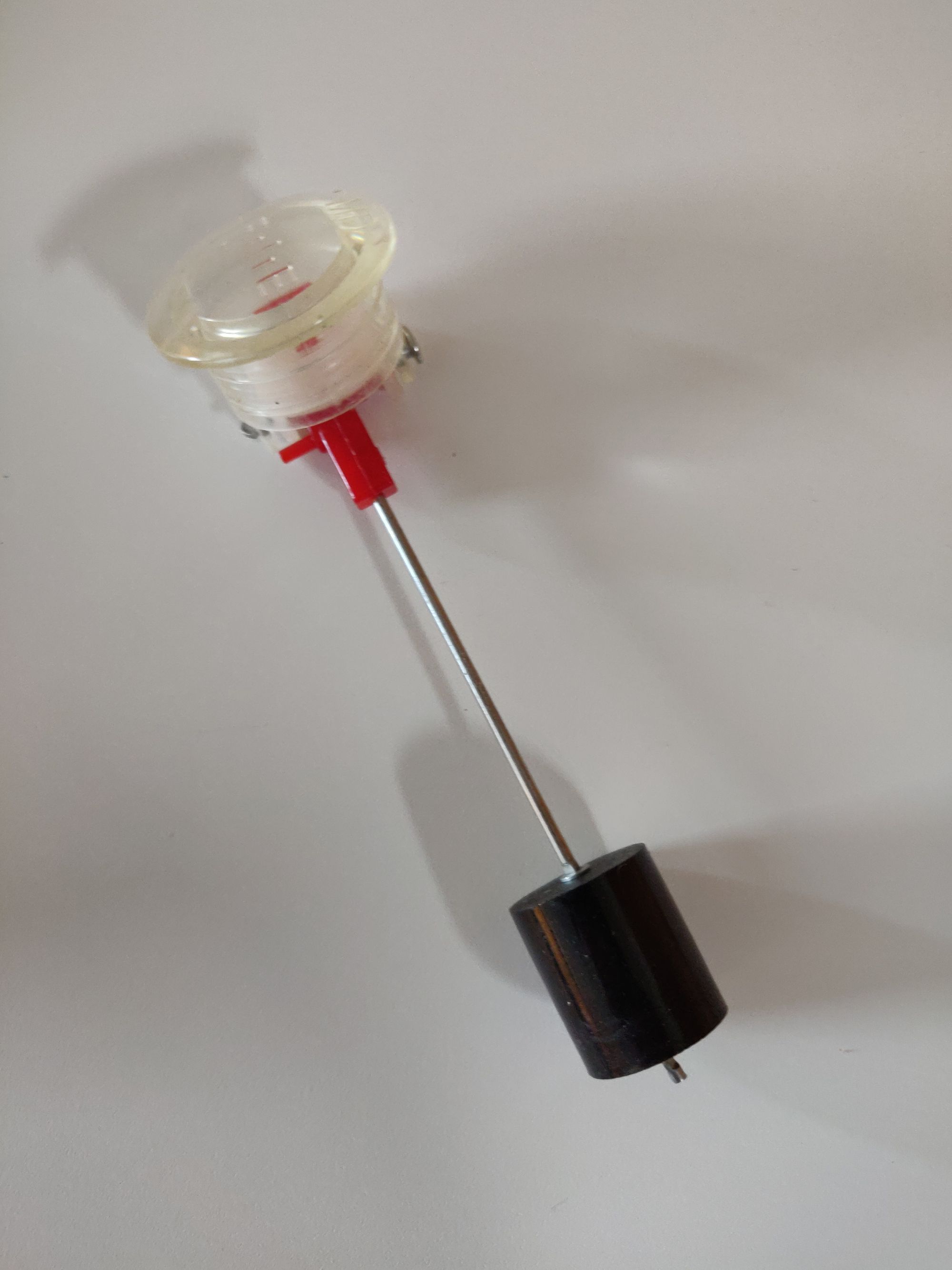
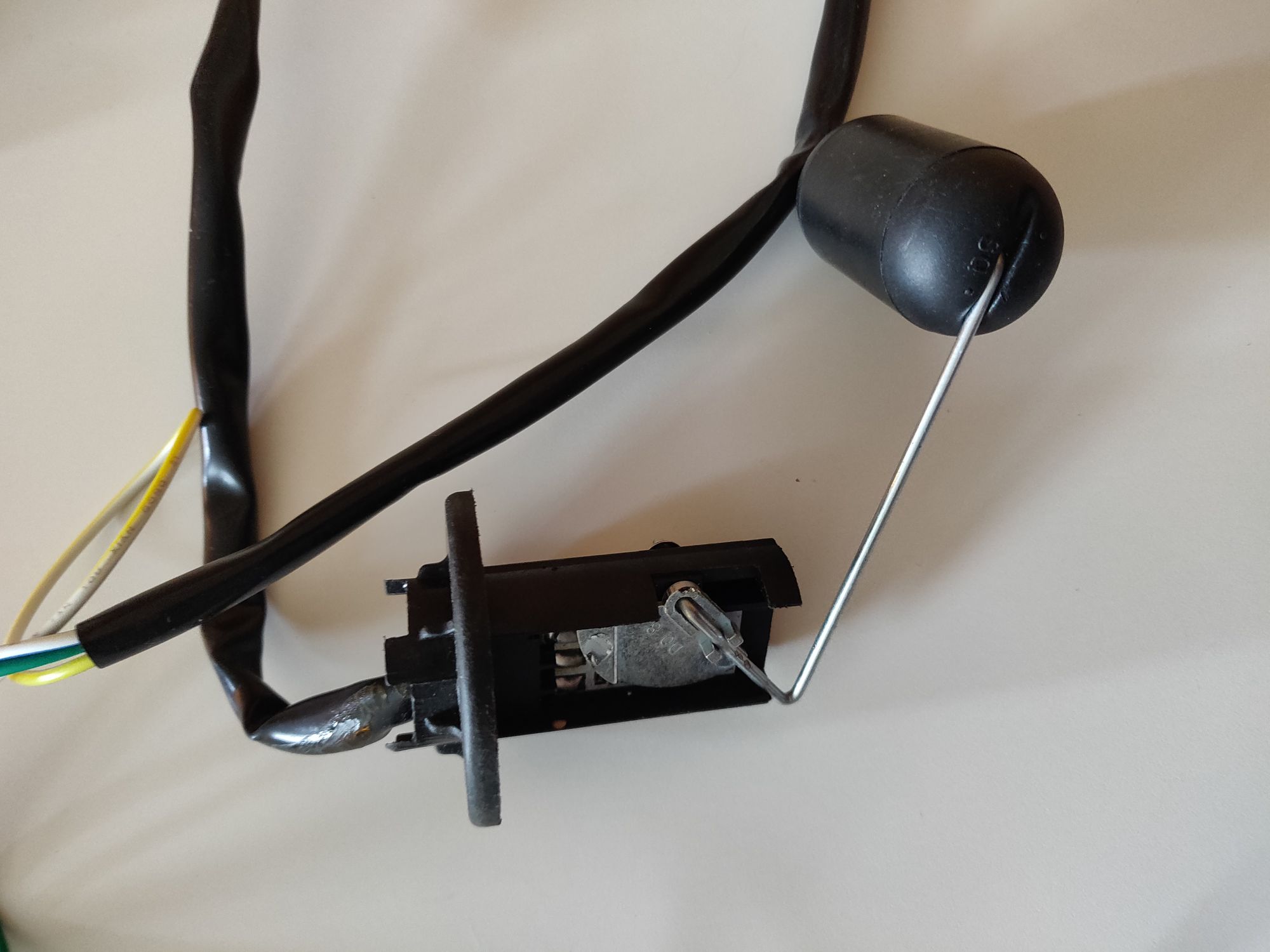
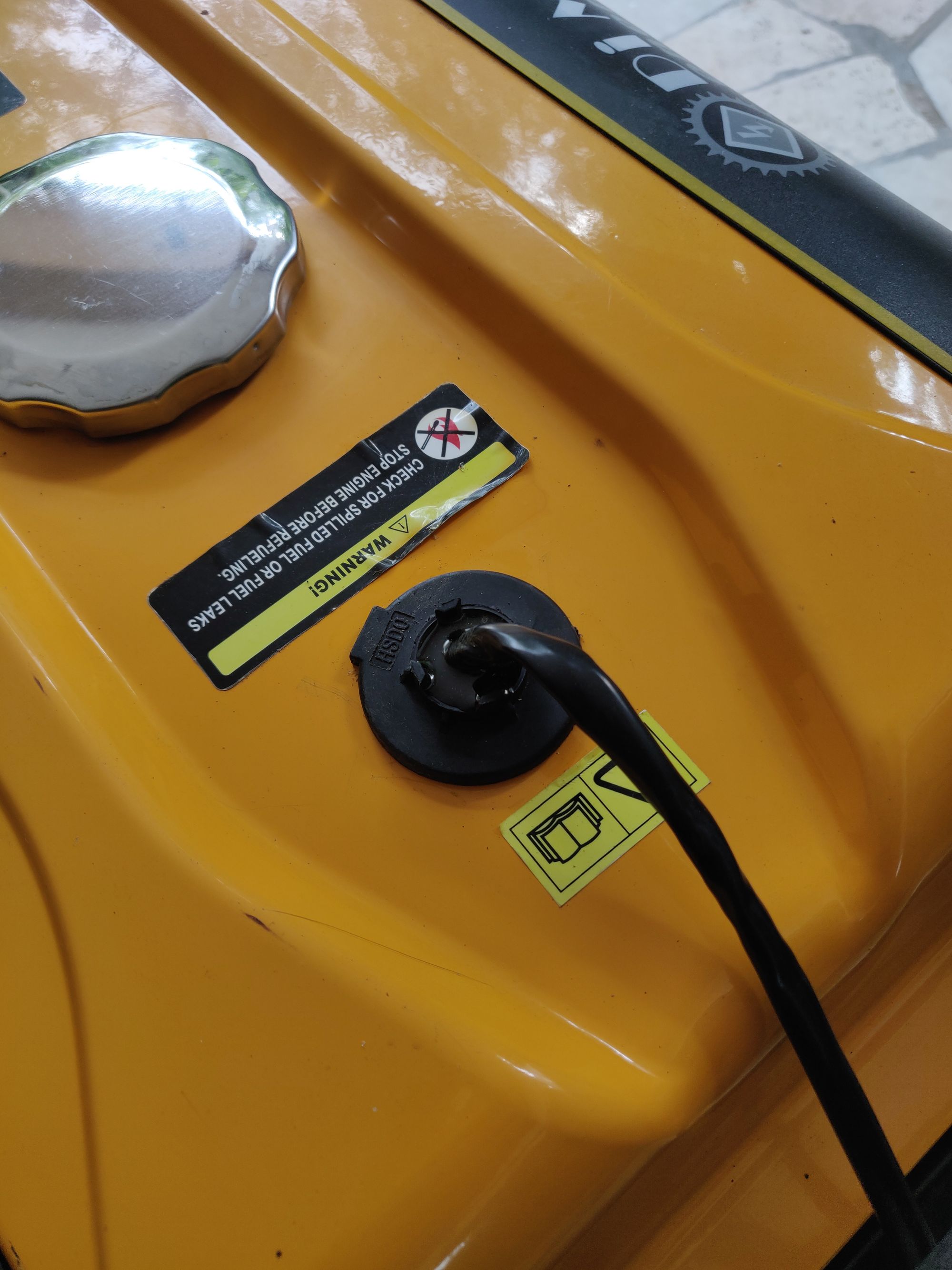
Replace the mechanical fuel level sensor with a potentiometer (can be found on eBay):
-
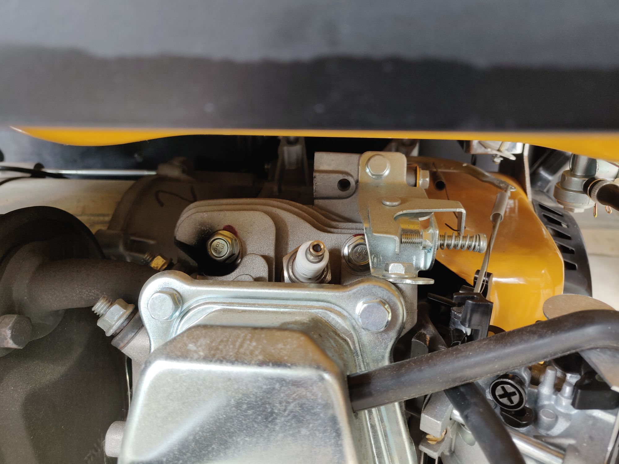
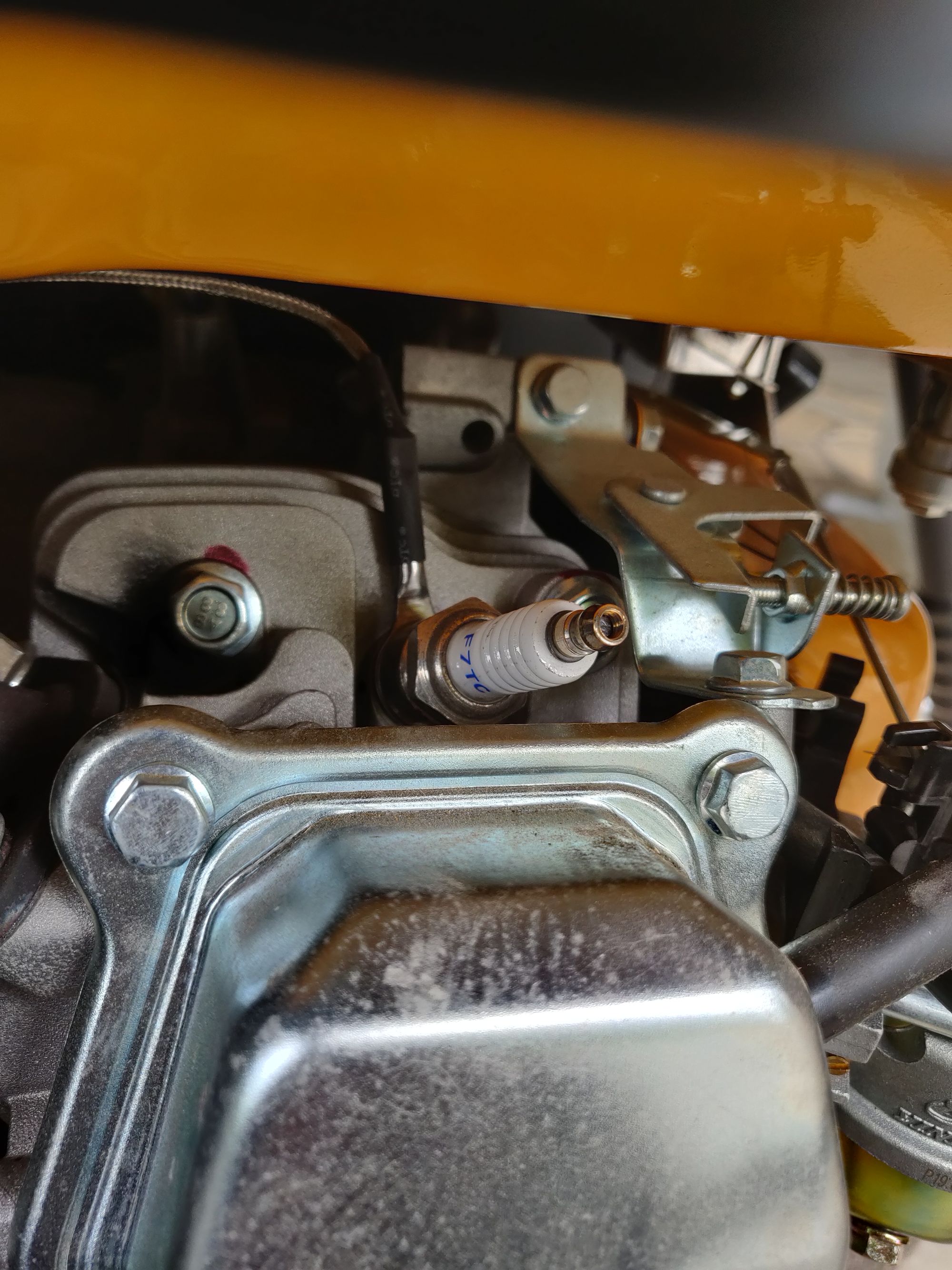
Add CHT sensor (spark plug thermocouple, can be found on eBay):
The CHT sensor is a K thermocouple and can be mounted directly under the spark plug, with its 14mm washer:
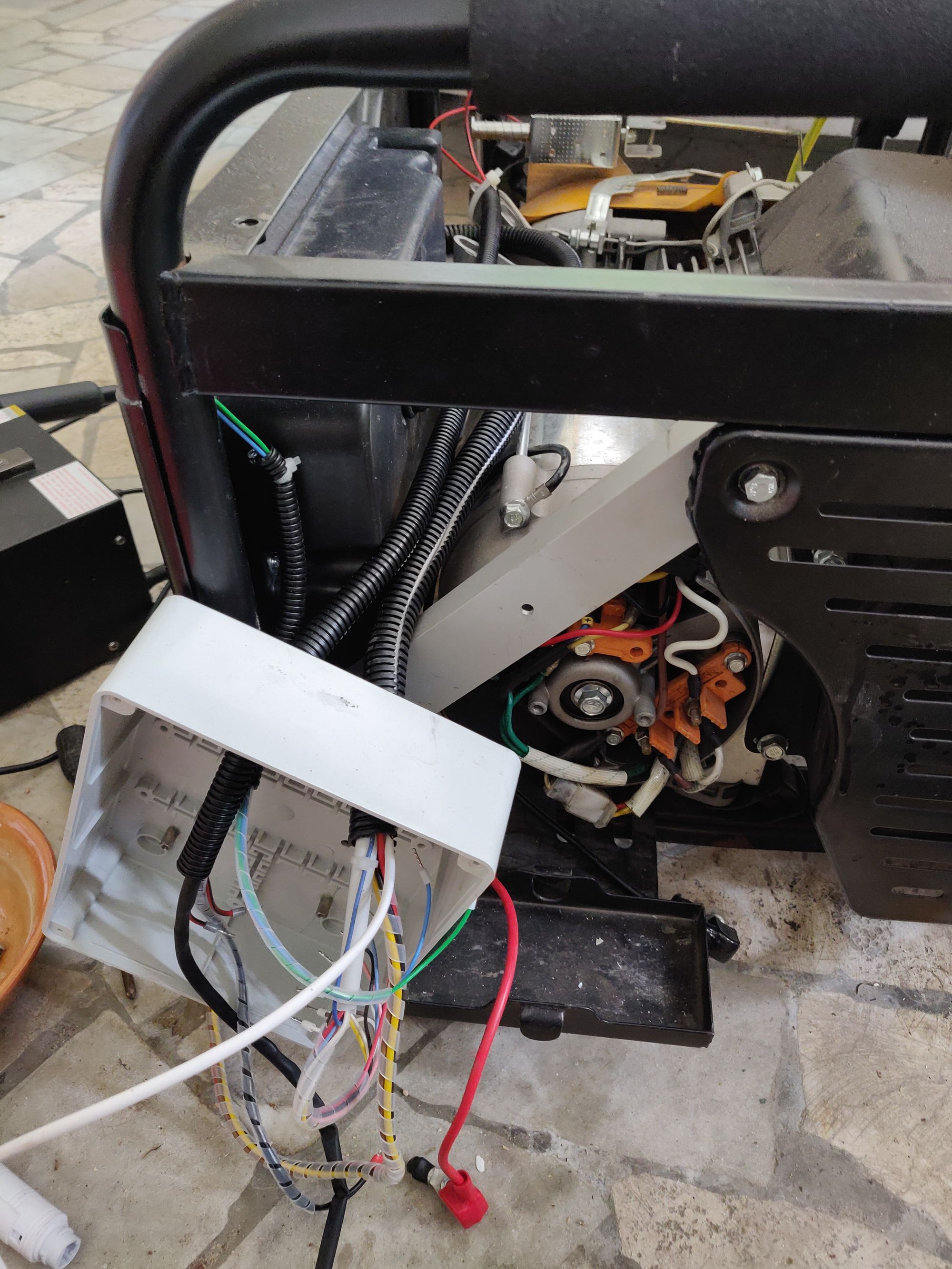
With new sensors in place, it's time to move on to the electronics. I had to reverse a bit the cabling of the generator, so I had to open the control panel:
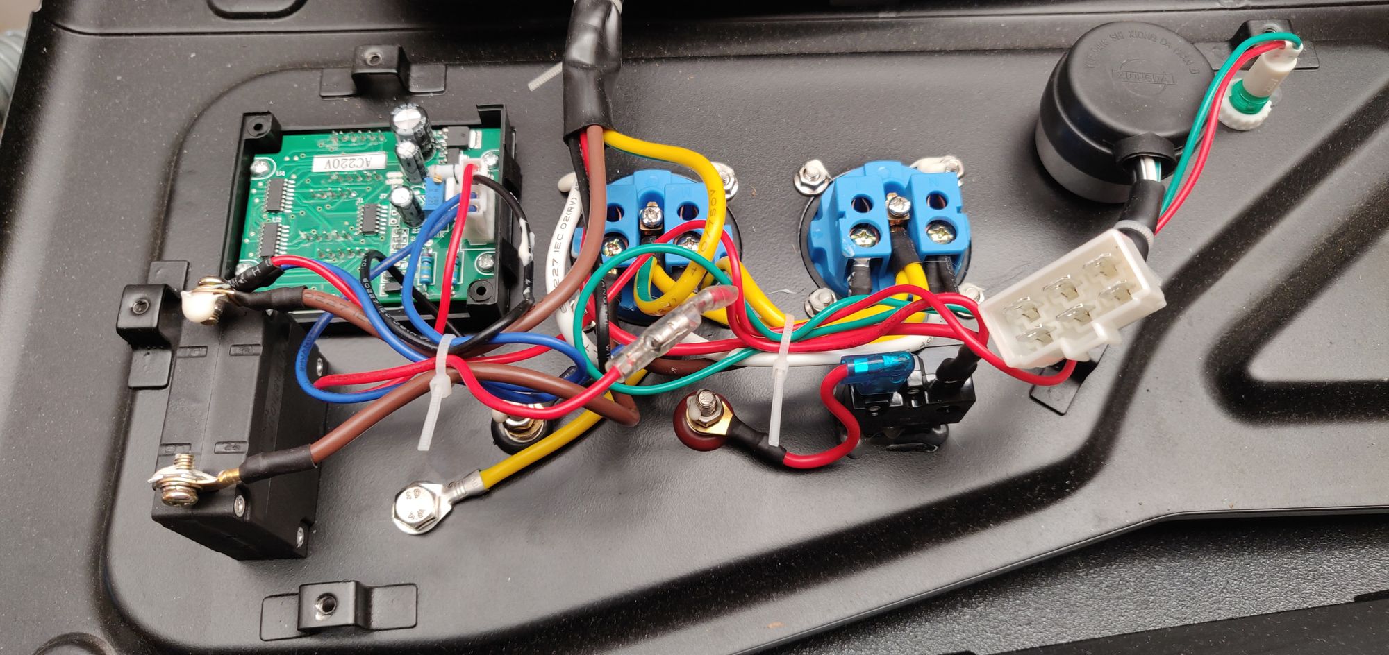
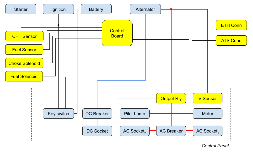
Follows a high-level diagram of the cabling:
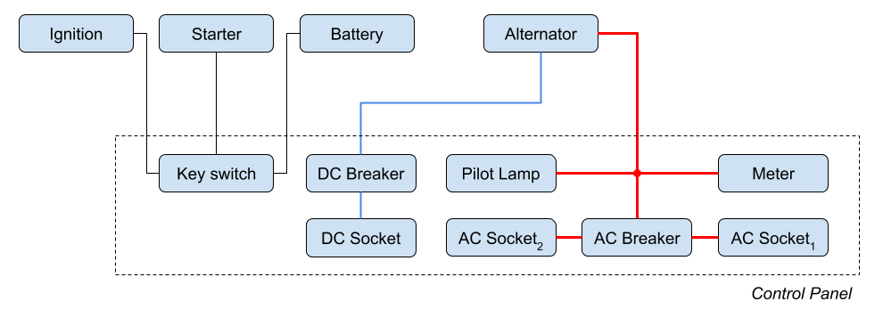
Here is the electronics upgrade plan - new components are highlighted in yellow:
I've decided to preserve the existing keyswitch, so one can use the generator manually, mapping the standard OFF/ON/START positions as follows:
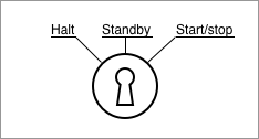
The "Halt" mode makes the controller switch off and ignore any ATS signal. In the halt mode the generator cannot start, and is reliably shutdown. For safety, the halt mode also preserves the original mechanical ignition-ground connection - so even in the unfortunate case where the controllar goes wild, the generator won't start.
The "Standby" mode makes the generator check the ATS line. If the contact is shorted, the generator will automatically start, until the line opens back.
The "start/stop" position is meant for manual use, and will make the generator start (or stop if it was already running).
Now let's move from theory to practice. I milled a pcb that fits exactly on top of the existing display meter, so to contain both the voltage sensor (ZMPT101B) as well as the output relay:
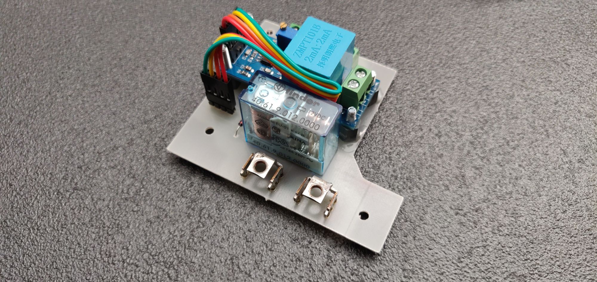
And then, I've installed it on the control panel:
To implement the control board, I've decided to use an Olimex STM32-E407 board, as I already had some of these lying around.
Let's recap the requirements here:
-
Ethernet connection
Not much to do, the E407 board includes a PHY and an ethernet connector. -
ATS connection
The ATS acts as a normally open switch. Through the 2-pole ATS connector, we sense when the ATS contact closes. This line should be protected from overvoltage. -
Battery
The E407 has a buck converter that will accept anything between 6 and 16V. However, when starting the generator, the starter engine is drawing a lot of current which gets the E407 rebooting - I had to add a reverse polarity protection diode and a big capacitor to supply power when starting. Also, the board should monitor the battery level - which is easily doable with an ADC input and a voltage divider. -
POE
I intend to keep the board always connected via ethernet (to be polled via snmp), so I don't want that to deplete the battery - hence the board should use POE as preferred power supply. Since the E407 doesn't support POE, I'll use a POE splitter (can be found on eBay) to power it. The firmware should be able to monitor the POE voltage (ADC again), so to be able to detect if there is no power over ethernet for a long period (and move to a suspended mode to avoid depleting the battery). -
Output relay
A high-current 12v relay, so that the board can decide when it's proper to switch the load on (like after warm-up, when the generator stabilizes). This allows the board to disconnect the load if operations are not under certain parameters (eg. unstabilized rpms). -
Voltage sensor
The board should monitor the output voltage and frequency. I've opted for a ZMPT101B module (can be found on eBay). This will roughly offset and scale the output AC voltage into the 0-5V range, so that we can feed it to the ADC. -
Starter
The board needs to switch on the power generator, so it needs to drive the starter relay via a MOSFET. -
Choke solenoid & fuel solenoid
Drive these via a MOSFET. The choke solenoid can only run for at most 2 seconds (by specs) - else you risk cooking it. So the idea here is to power on the solenoid so that it opens the choke for 1 second, and then modulate the power via PWM so to keep the choke open without overheating. Because of the solenoid size, a beefy flywheel diode is needed to dissipate the energy it gives back when switching off (can be up to serval amps at 12V). A similar logic is applied to the fuel solenoid, which is kept open with a ~30% duty cycle with running engine. -
Ignition
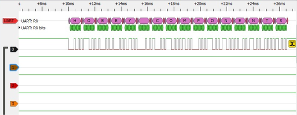
The board should be able to switch off the generator when needed. To switch off a Honda GX* (and clones), you simply ground its ignition coil and temporarily disable the spark plug. As almost everything else in the board is solid state (except the output relay), I wanted to keep a solid state solution so I went on peeking at what we find on the ignition line: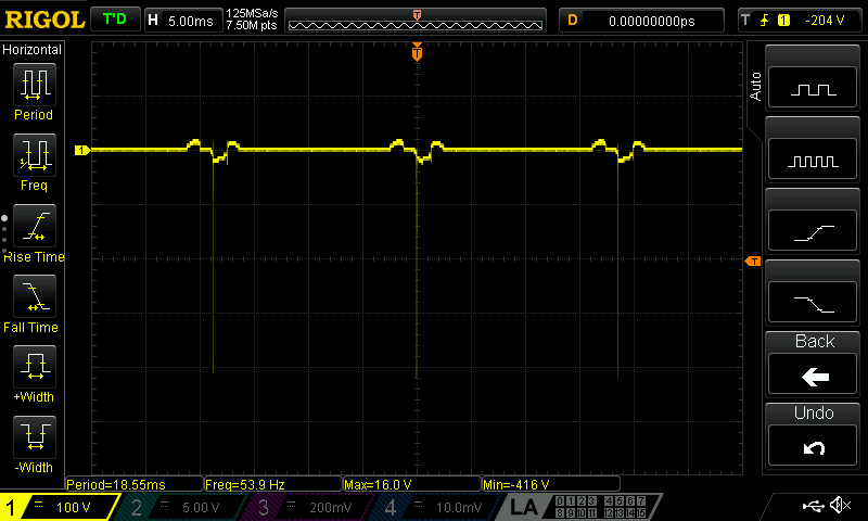
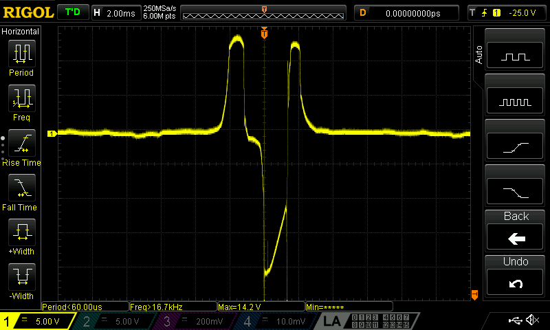
Besides the -416 volts (inductive) spike, the main wave oscillates between +16 and -20 volts. I've opted for an optocoupled triac snubber to short the ignition to ground.
-
Fuel level sensor
The level sensor presents itself as a potentiometer (in reality it's not :( - it's a rotary switch), so it can be read via an ADC. -
Cylinder head temperature sensor
The board should dected overheating and properly switch off the generator to avoid any unsafe operations. I've opted to use a MAX31855K to read it.
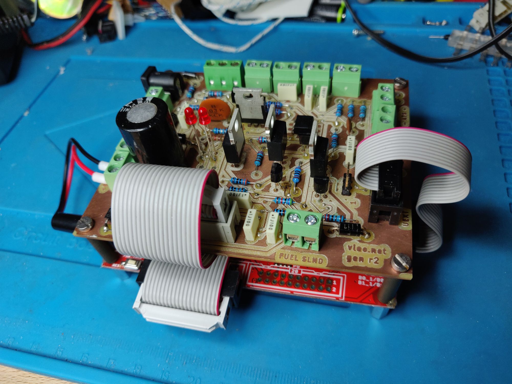
Said so, I've milled a prototype board. It's designed to fit exactly on top of the E407, so that the two can be stacked together:
- Controller board schematics
- Milled PCB:
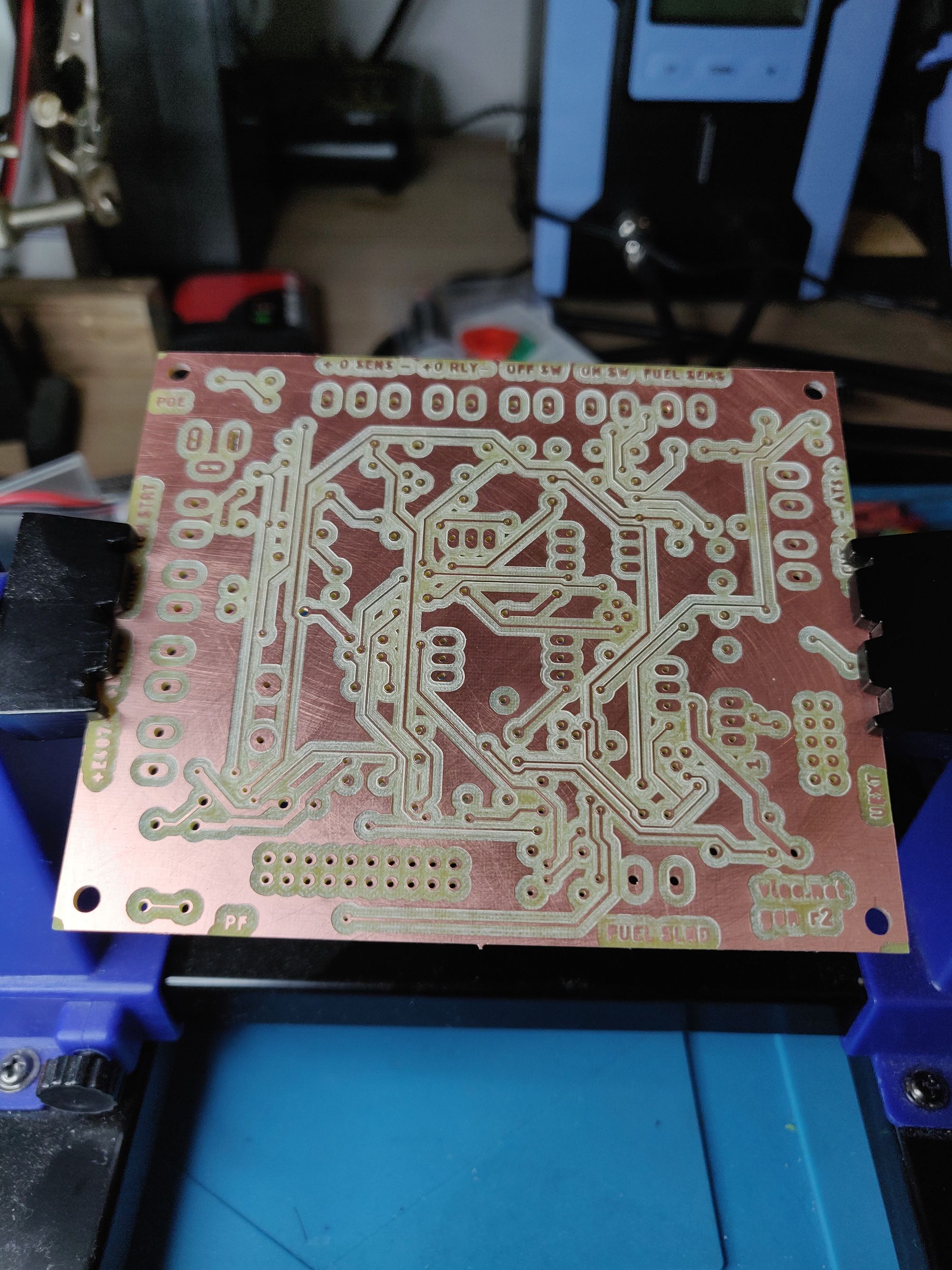
- Board assembled and stacked on top of the E407:
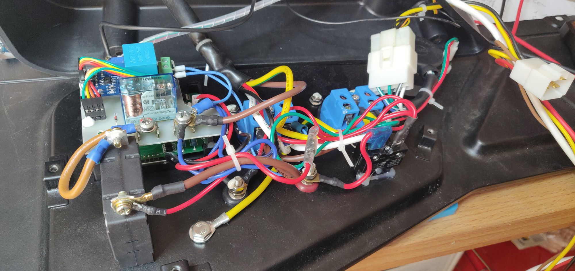
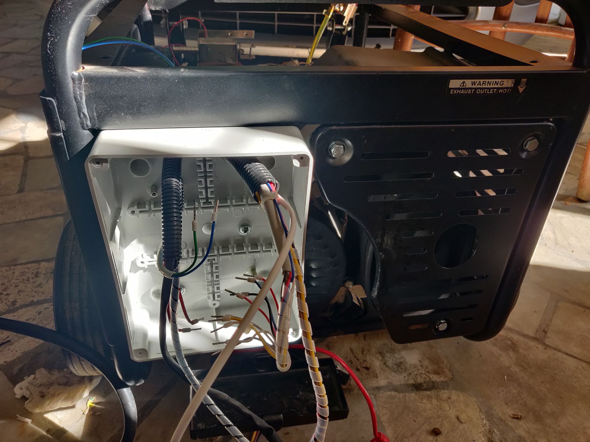
Now it's time to put it all together. Let's do some proper cabling:
I've decided to host the controller board in a waterproof junction box just on top of the battery. Let's add a support to the frame, so that there's something to hook the box:
I've added then the controller and the POE injector in place:
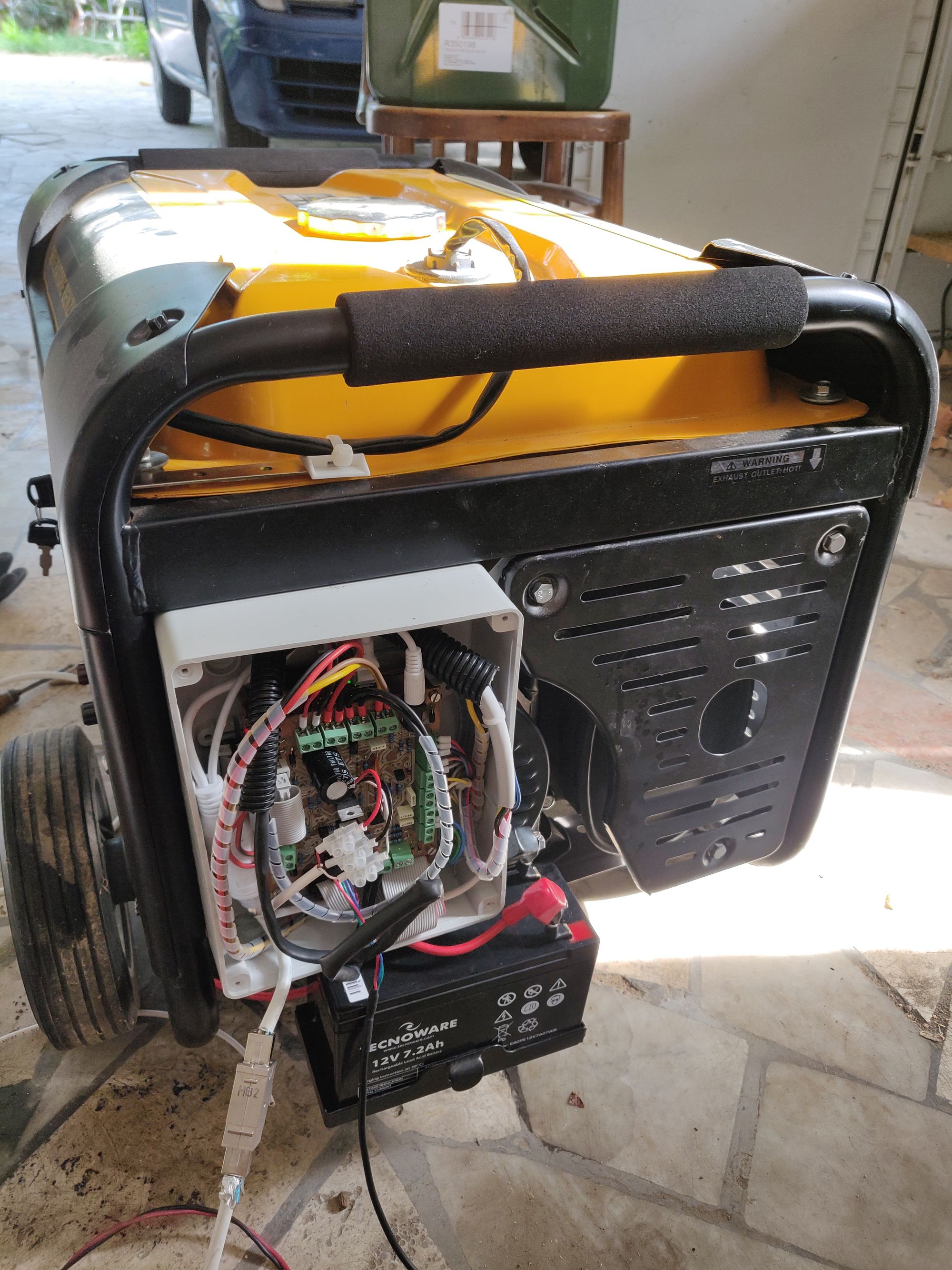
And here we are:
Since the pilot lamp was not really useful - it was super weak - I've replaced it with 3 high brightness leds: the controller uses 2 of them to provide visual feedback to the user, while the third one is hooked to the 220v output line (with a properly sized resistor).
Now that everything is ready, let's test the "manual" mode:
For the firmware I've used a plain configuration (no OS). I took some care to ensure that I can tweak the firmware also when I'm remote, so I've setup the followings:
- An embedded bootloader to update the firmware via TFTP;
- Independent watchdog to reset the controller, shall any bug arise;
- Read and expose metrics via SNMP, REST and Prometheus endpoints;
- Remote "start/stop" via REST API;
- Control logic implemented as a layered state automaton.
I like the idea of controlling the generator via curl :)
aleofreddi@macmini ~ % curl -s http://gen-dr/power | jq .
{
  "controller_status": "HALTED",
  "engine_status": "POWERED_OFF",
  "uptime": 8478441
}
aleofreddi@macmini ~ % curl -s http://gen-dr/sensors | jq .
{
  "battery": {
    "raw": "2603",
    "value": "12.033527",
    "unit": "V"
  },
  "poe": {
    "raw": "2527",
    "value": "11.688732",
    "unit": "V"
  },
  "fuel": {
    "raw": "1983",
    "value": "76.272575",
    "unit": "%"
  },
  "output/voltage": {
    "raw": "0",
    "value": "0.000000",
    "unit": "V"
  },
  "output/frequency": {
    "raw": "0.000000",
    "value": "0.000000",
    "unit": "Hz"
  },
  "temp/internal": {
    "raw": "25697856",
    "value": "30.256126",
    "unit": "C"
  },
  "temp/cht": {
    "raw": "25697856",
    "value": "24.542288",
    "unit": "C"
  }
}
aleofreddi@macmini ~ %
ATS Panel
As anticipated before, I'm using a Datakom DKG-175 to transfer the load to the generator when needed. The DKG-175 will fit in any standard DIN box, and requires a couple external relays (I took the occasion to recable a patch panel as well):
Final test
Now it's time to put all together! I've located the generator in the basement (NOTE: carbon monoxide kills! Place you generator far away from your home!).
I've connected the exhaust with an existing flue previously used by a decommissioned diesel boiler, and it turned out that with the generator noise level drecreased considerably, so there is no need for a baffle box as originally planned.


